

The Bologna data centre (DC) network was deployed in 2021 and began carrying operational traffic towards the end of 2022, providing a robust foundation for ECMWF’s critical services. As a new site, Bologna offered an opportunity to build and test new infrastructure alongside the live operational systems in Reading, addressing known shortcomings and validating new designs before services were migrated.
The experience of operating the network 24/7, including during the large-scale migration of services, highlighted areas where the architecture could be strengthened. Some elements had become more tightly coupled than originally intended, allowing faults to propagate and increasing the risks associated with network changes and maintenance. The network was temporarily operated at reduced capacity while these issues were investigated.
Internal and external reviews, gap analysis and investigations with manufacturers identified a series of enhancements. Together with the requirements of the new high-performance computing facility (HPCF), the growing role of artificial intelligence (AI), and wider service developments, these lessons are shaping the next stage in the evolution of the DC network architecture.
This article describes the improvements introduced to enhance resilience and stability, and sets out the architectural principles that will guide the network’s future ahead of the next HPCF commissioning.
Architectural enhancements to the current network
The original architecture was based on an IP Fabric design, also known as Spine-and-Leaf or Clos Network, named after the electrical engineer Charles Clos (Clos, 1953). Unlike a traditional three-level topology consisting of core, distribution and access layers, an IP Fabric architecture consists of just two layers – leaf switches that are used to provide endpoint connectivity and spine switches that are used to provide a fast interconnect between the leaf switches. A specialised pair of leaf switches, called border leaf switches (BLS) provide an interconnection point between an IP Fabric and other significant infrastructure, such as Internet edge routers (IER), HPC complexes, security appliances, and application delivery controllers (ADC). Data centre interconnect (DCI) functionality between different IP Fabrics is also implemented on the BLS.
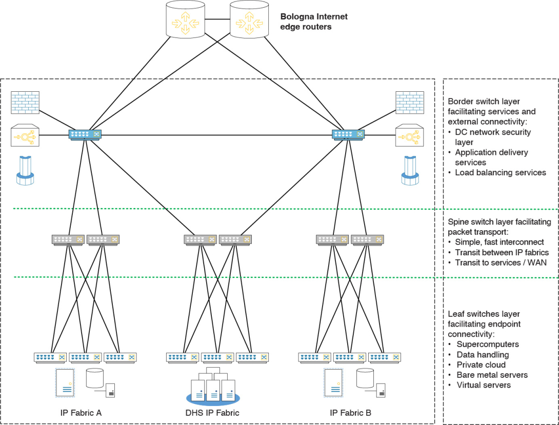
The original ECMWF design envisaged two main IP Fabrics dedicated to serving most of the general-purpose and operational workloads, interconnected to a third IP Fabric dedicated purely to the Data Handling System (DHS) infrastructure (Figure 1). All three IP Fabrics were designed to be independent and loosely coupled, thus constituting separate failure domains. This design feature ensures that a fault within a single IP Fabric would not propagate to a different part of the infrastructure.
HPC edge router (HER) deployment
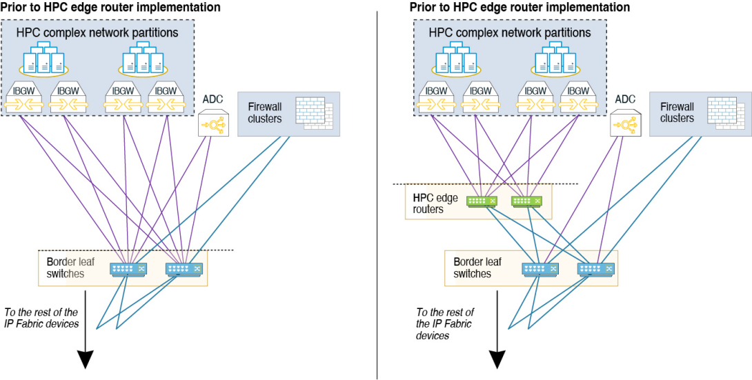
One issue identified during operations was that the HPC interconnect design could place a substantial load on the control plane of BLS devices. This reduced the network’s ability to update and synchronise routing information across IP Fabric devices, thereby resulting in network connectivity issues. The original design for the HPC interconnect had to be changed during HPCF commissioning due to limitations in the InfiniBand-Ethernet gateways used in the Atos solution. Instead of a standard routed interconnect configured on each of the main IP Fabric’s BLS, large broadcast domains (networks where messages from one endpoint can be heard by all other endpoints) had to be presented on the BLS devices. This meant that a large number of MAC Address to IP Address mappings had to be processed and signalled to the rest of the IP Fabric devices. The signalling of these mappings increased the central processing unit (CPU) load on BLS devices and was the reason why the network protocol convergence was impacted. To rectify this, new pairs of devices known as HPC edge routers (HERs), dedicated solely to aggregating InfiniBand gateway connectivity and presenting a routed interconnect to the BLS, were introduced in between IP Fabrics and HPCF InfiniBand gateways (Figure 2). This design adjustment helped in stabilising the control plane on the BLS devices at the cost of slightly suboptimal bandwidth utilisation and increased failover time.
Operations Shortcut Network (OSNET) deployment
While the HER deployment improved network stability, additional measures were needed to reduce operational risk and ensure service continuity during major faults or maintenance activities.
The main problems encountered were mainly related to the core elements in the network BLS devices with their interconnects to the firewalls. Even carefully planned changes carried a relatively high risk that failure might involve an unacceptably long period of recovery. To mitigate this risk, additional network infrastructure was implemented as an interim measure.
Known as the Operations Shortcut Network (OSNET; Figure 3), it provides a manually triggered alternative data path that supports operational dissemination activities during an emergency or a significant IP Fabric fault. This solution required additional network devices strategically connected to critical components of DC infrastructure, alongside existing connections to IP Fabrics. This enables traffic engineering to redirect traffic when required.
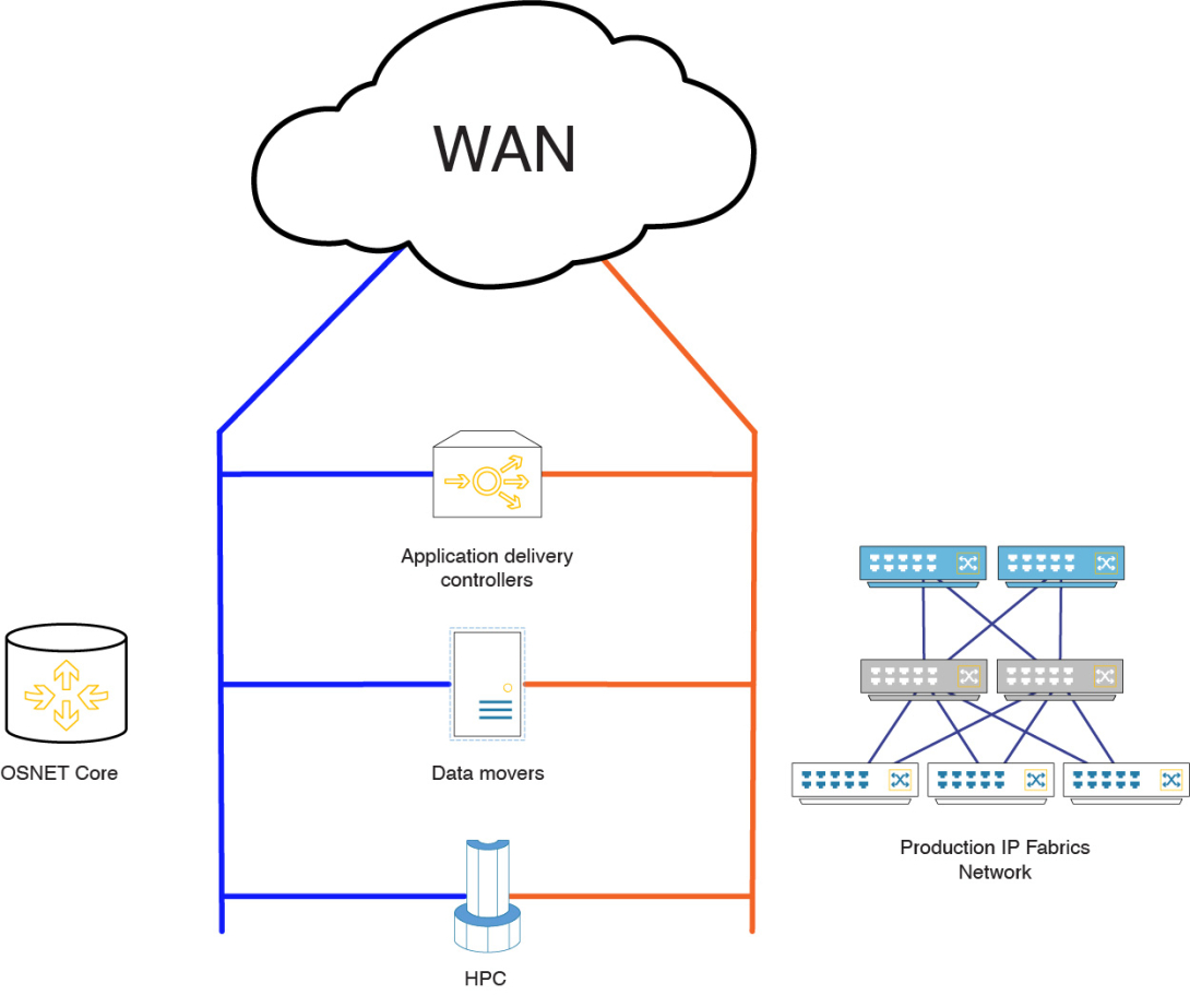
The OSNET provided a simple but effective fallback path, maintaining 24/7 essential service delivery under exceptional circumstances. It has allowed us to progress rapidly in eliminating the single point of failure, as well as perform important maintenance actions, for example IER upgrades.
Edge leaf switch (ELS) implementation
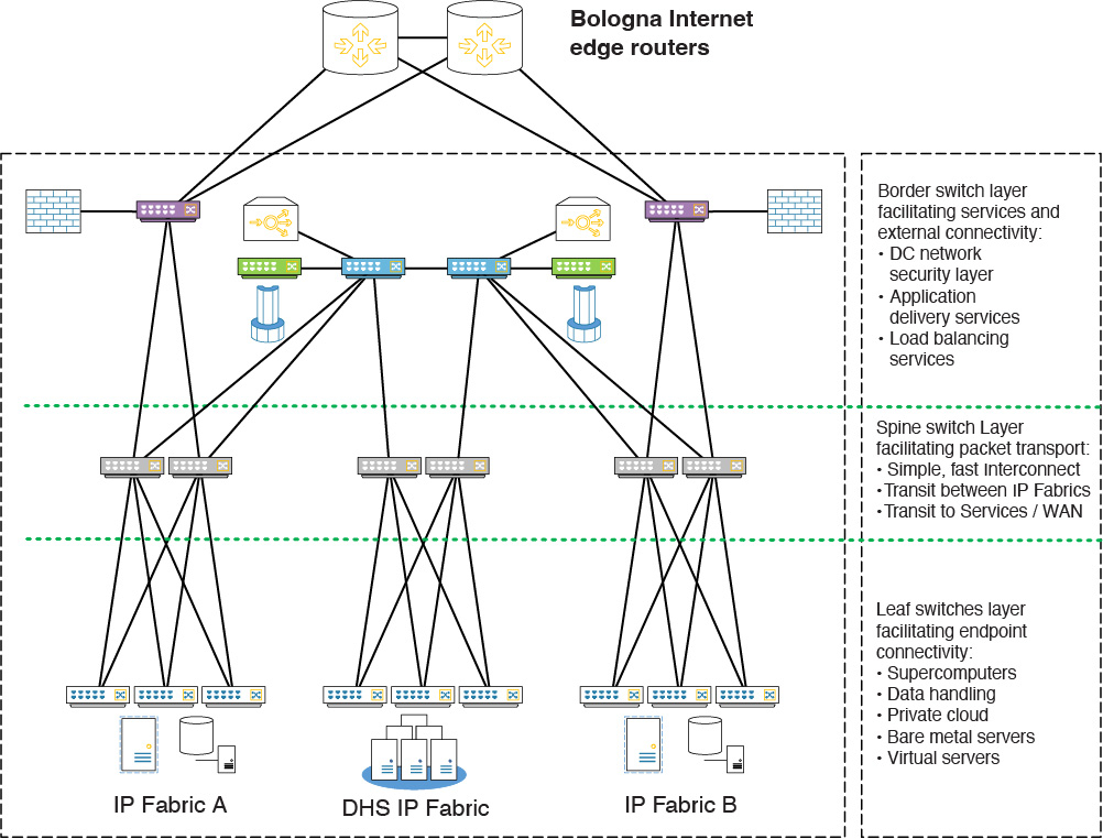
The commissioning of OSNET paved the way for further changes to stabilise the DC network and remove the single point of failure. As a significant enhancement to the original design, a new pair of devices was introduced into each of the IP Fabrics, and IER and DC firewall connectivity was migrated to this new infrastructure. This reduced the size of the failure domain in the event of BLS switch instability and supported decoupling the IP Fabrics, as per the original DC network architecture design.
This modification incorporated feedback from the various technical design reviews and operational experience. It meant that the interconnect between DC firewalls and ELS switches was refactored to be less prone to issues compared to the original BLS to DC firewall implementation.
The final stage of this work was the migration of the IP Fabrics towards fully separate failure domains. This included reconfiguring each firewall cluster to connect to a single IP Fabric, further reducing the probability of shared failure scenarios. Figure 4 shows the current DC network, including all enhancements described (HER and ELS), following the firewall cluster reconfiguration.
Removal of stretched broadcast domains
In parallel to hardware-based changes, significant effort has been invested in further decoupling the IP Fabrics, as envisaged in the original design, by removing broadcast domains that were “stretched” between both main IP Fabrics.
This is important because stretching of broadcast domains requires constant information signalling across all involved IP Fabrics/network devices, thereby introducing fate-sharing.
Nearing completion, this transformation remains a complex and lengthy process requiring significant effort from infrastructure and service owners, as their existing designs have to be refactored. Completion is anticipated by the end of 2026.
Key lessons from operating the Bologna DC network
Several lessons have been learned from building and operating the Bologna DC network:
- Fault propagation between independent areas of the network can significantly increase outage scope and time to recovery.
- Complexity breeds fragility.
- Flexible and consistently applied traffic engineering enables rapid failover with predictable and well-understood operational impact.
- Automation tooling, together with testing and development environments, greatly aids in planning and derisking major network changes.
The vision for the future architecture
Whilst continuing to strengthen the existing DC network, the longer-term evolution is an equally important consideration, as the original network design was completed in 2019. This must reflect the growing operational requirements, including the next HPCF, advances in AI, and wider developments in network technology.
A significant amount of preparatory work has been carried out to analyse requirements from current and future users, services and major projects, whilst drawing on years of operational experience gained from running the Bologna and Reading data centres. These activities have shaped the high-level design criteria for the next DC network:
- Modularity: networks and services should be broken down into functional blocks, each representing an independent failure domain, with the aim that an issue in one functional block would not affect any of the others.
- Simplicity: functional blocks should be interconnected in a simple and consistent way, providing very loose coupling to improve interoperability, reduce complexity, and thereby reduce fragility.
- Scalability: security layer infrastructure should consist of multiple smaller appliances clustered together to deliver high throughput from the whole cluster, enabling easier horizontal scalability as bandwidth demands increase.
- Flexible traffic engineering: the underlying network should provide the capability to apply security controls to the vast majority of traffic flows, whilst permitting certain well-defined traffic flow to bypass centralised security controls as an exemption.
- Automation, testing and development environments: manual configuration of devices should be minimised (ideally eliminated) and new architecture should move towards the Infrastructure-as-Code paradigm. This should be complemented by physical and virtual environments that will enable modelling and testing of both business-as-usual and major network changes.
Based on these criteria, a new architecture that represents an evolution of the existing DC network has been designed.
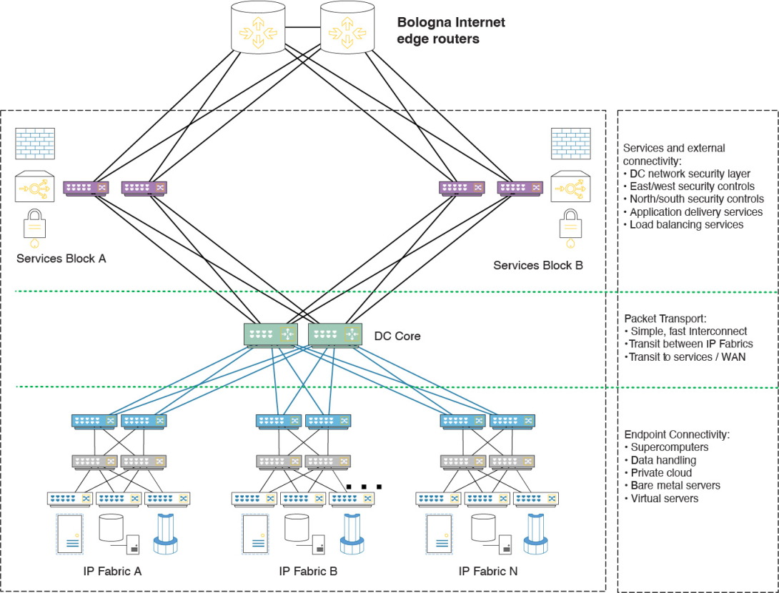
The fundamental building blocks will be the deployment units (DUs). Each DU will utilise the network topology build of platforms best suited to the workload it serves. This will optimise investments and ease future potential vendor integration, as there will be no hard requirement to reuse the same platform/vendor between the DUs.
The DUs will be interconnected via a simple DC core responsible purely for packet forwarding. This will simplify the interconnect between DUs and reduce configuration complexity at the DC core network. Security appliances, application delivery controllers and other auxiliary services will be centralised in a redundant pair of service DUs, simplifying the configuration of other DUs and easing application of security controls.
At the same time, platforms within each DU will have sufficient intelligence to locally apply a limited number of security controls to well-defined traffic flows. This will enable high-volume traffic to be forwarded efficiently between endpoints in different security zones, either within the same DU or between different DUs. Finally, the solution will use non-proprietary network protocols throughout, improving cross-vendor compatibility and reducing fragility.
The future DC network, represented in a similar way to the current design, is shown in Figure 5.
Key differences between the current and future architectures
The proposed architecture introduces several important improvements over the current design:
- Decreased coupling between individual IP Fabrics, reducing failure domain size, thereby reducing downtime and derisking network changes and maintenance activities.
- Centralisation of services, resulting in symmetric and predictable traffic patterns within the DC network, easing troubleshooting activities and improving capacity planning.
- Improved traffic engineering, allowing for well-defined high-volume traffic flows to be forwarded natively, without having to be inspected by security appliances.
- Increased upgradability, as each individual DU/DC core can be horizontally scaled and upgraded individually, without necessitating the replacement of all other devices.
- Increased use of automation tooling and testing/development environments.
While the architectural vision is still under development and validation with the service owners, the design is expected to be finalised in late 2026 with deployment and testing to commence in 2027. The overall topology allows most of the current network devices to be reused, maximising return on investment and enabling a gradual transition towards the new architecture. The final implementation of the design and migration of services to the new architecture will be described in a future article.
Further reading
Benallegue A., S. Burlakov, G. Margaritis, H. El Ghouizy and M. Di Mascolo, 2022: ECMWF’s new network and security infrastructure. ECMWF Newsletter No. 172, 35–40. https://doi.org/10.21957/abc631j7s2
Clos, C, 1953: A study of non-blocking switching networks. The Bell System Technical Journal Vol. 32, issue 2, March 1953.
https://ieeexplore.ieee.org/document/6770468